Automatic Top-Off Unit
Personal project
I designed this system of float switches and relays to drive a pump to replace water in my saltwater aquarium as it evaporates. As the water evaporates, an equal volume of fresh water must be added to maintain the salinity. The top-off system includes a failsafe system in the case of switch malfunction.
I wrote an in-depth writeup/tutorial intended for other aquarium owners. The writeup includes wiring diagrams and system state explanations. The writeup can be found here: https://www.nano-reef.com/forums/topic/373184-ato-cheap-safe-well-explained/ and reproduced below.
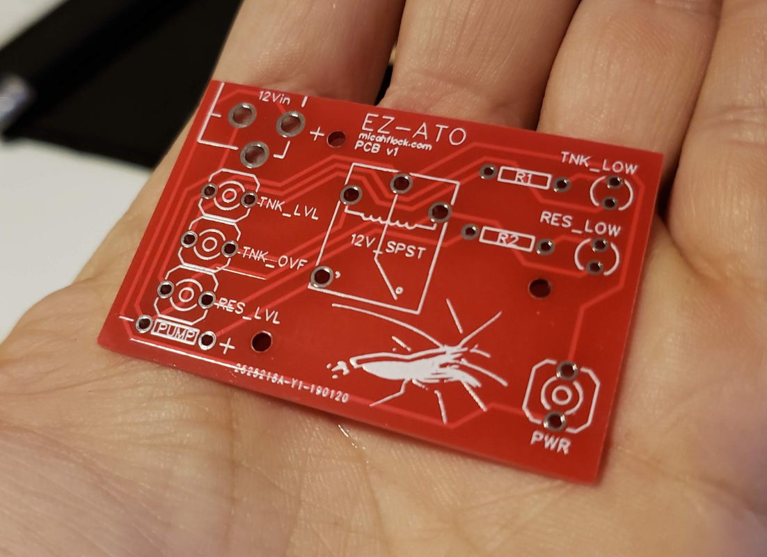
I later designed a PCB to neaten up the wiring, also below.
I'm going to include a medium-detailed writeup, in case someone needs to use it as reference. This is all synthesized from various sources around the internet, but I figured it'd be nice to have it all in one place.
First, the circuit schematic:
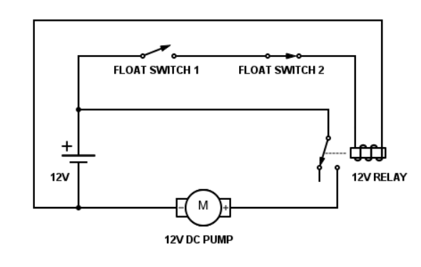
Basic Idea: When the water level falls, it closes Float Switch 1 which sends voltage across the relay. That closes the relay, allowing power to reach the pump, filling your tank with water. When the water level rises again, the switch opens and the power to the pump is cut.
Check the bottom of this post for a more detailed explanation about switches and states, including how the failsafe works.
Float Switches: I use two float switches for redundancy, one placed at a higher level than the other. They could both be at the same level, it doesn't really matter. The switches are wired in series, so if just one of them is open, the pump won't turn on. I sourced the float switches from amazon at about $4/switch.
The Relay: The relay is used to control power delivery to the the pump. I can't just use a switch, as the pump will draw (significantly) more current than the switches are rated for, which is very dangerous. https://en.wikipedia.org/wiki/Relay#Basic_design_and_operation is a good place to find more information about how relays work. I used a 12V automotive relay, a little under $5 on amazon.
The Pump: I chose a 12V brushless DC submersible pump to lift the water into my tank. Brushless pumps tend to last longer and be quieter than other options. $9 on amazon.
Power Source: I used a standard 12V power supply. There are a lot of options, I chose one that included an adapter to connect it to the rest of my circuit, which ended up being very useful. $7 on amazon.
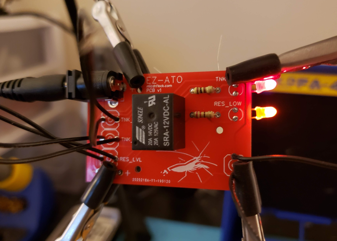
Below is the whole circuit connected and set up for testing:
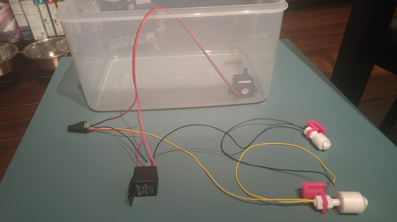
I glued the pump into the bottom of a large (3 gal) BPA-free Tupperware container (by far the most expensive part of this ATO, at $20). The bright pink things you see the float switches attached to are 3D printed brackets I made to attach them to my tank.
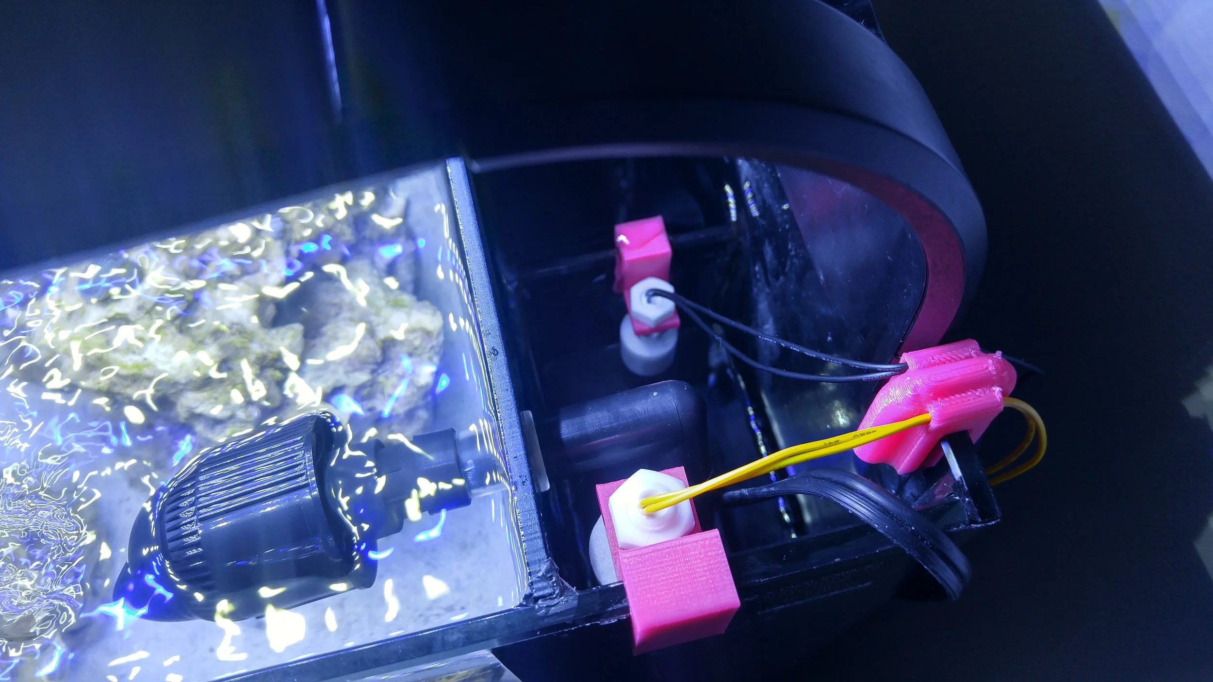
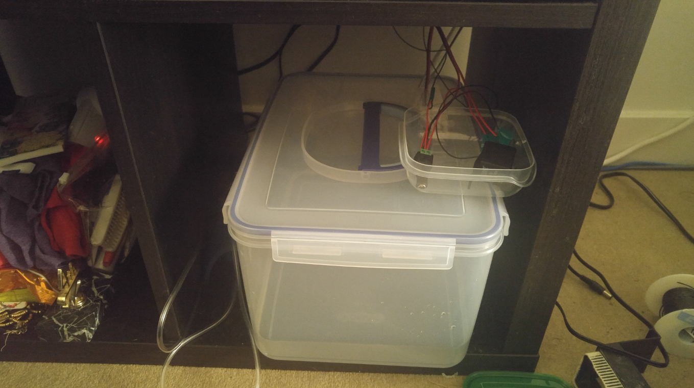
Here's a shot of the ATO reservoir under my tank:
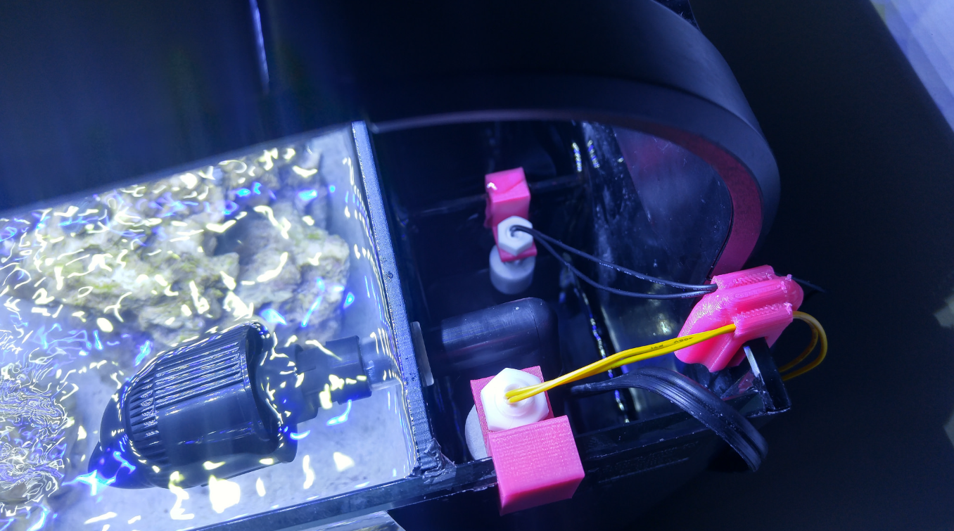
And a shot of the float switches:
More detailed explanation of how this works:
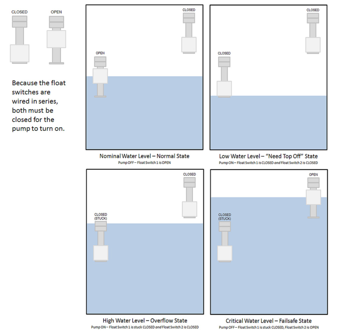
The "normal" state of the system is (with float switch 1 being the primary and float switch 2 being the backup):
Water Level: Nominal, the water level I want my tank to be.
Float Switch 1: Open, because the nominal water level raises the float to open the switch.
Float Switch 2: Closed, because the nominal water level is not high enough to open it, it is set to open when water reaches critical levels
Pump: Off
The "top off needed" state of the system is:
Water Level: Below nominal, due to evaporation.
Float Switch 1: Closed, because water level has fallen below nominal
Float Switch 2: Closed because the water level is even lower than "normal" system state
Pump: On
Once the pump turns on in the "top off needed" state, the water level rises until it is high enough to open Float Switch 1 and return the tank to the "normal" state.
However, if for whatever reason the water doesn't open Float Switch 1 at the nominal level, then the pump stays on and the system enters the "Overflow" state.
"Overflow" system state:
Water Level: Above nominal
Float Switch 1: Closed, because it is stuck closed even though water level is above nominal
Float Switch 2: Closed because the water level has not yet reached critical levels
Pump: On
In the "Overflow" system state, the pump stays on and the water level continues to rise even though the water level is above nominal. This is because Float Switch 1 is somehow stuck closed. The water level is not yet critical. As the water level reaches dangerous levels, the system enters the "Failsafe" state.
"Failsafe" state:
Water Level: Critical
Float Switch 1: Closed, because it is stuck closed even though water level is above nominal
Float Switch 2: Open, because the water level has reached critical levels, where this switch is set to open.
Pump: Off
For water to actually overflow out of the system, both Float Switch 1 and Float Switch 2 should have to get stuck closed.